VALVE - TRAIN COMPONENTS
SUPERIOR QUALITY, RACE & STREET PROVEN
![]()

![]()
|
Yella Terra roller rockers are
designed to allow fitment to the listed engine without
difficulty. Yella Terra roller rockers are substantially
stronger and more rigid, than production components, they
minimise valve guide and stem wear and reduce friction because
of the roller tip and roller bearing fulcrum. |
Rockers are mounted in two basic forms – stud mount and shaft or pedestal mount. We recommend the shaft mount or pedestal mount EASY FIT 'EF' range where possible, which bolt onto existing mountings, they have been proven to offer the strongest and most stable valve actuating system. For outright competition applications our heavy duty race shaft mount models are exceptionally strong and should be used where high lift cams and high rpm's are used. |
![]()
|
If you are undertaking substantial
engine modifications, you need to carry out a series of tests to
ensure compatibility to avoid damage. The manufacturers of Yella
Terra rocker arm systems are aware that the incorrect
installation of components can cause a lot of frustration. We
hope these hints will help to avoid problems. All engine builders, and assemblers, must be aware there are hundreds of possible combinations of components and modifications, over which the manufacturer has no control, they may have the potential to improve power – or if improperly assembled – to destroy an engine. |
Areas that can cause clearance problems between valves, block
and pistons are…
|
![]()
|
This clearance should be checked
after the camshaft timing has been checked and set, and should
be rechecked if the cam is subsequently advanced or retarded, or
if a cam with different lobe centres or duration is installed. The best method for checking valve to piston and block clearance is with plasticine or modelling clay. Stick a 1/4" thick strap of clay to the piston and block in the potential valve contact area. Oil the valves to prevent sticking when the valves contact the plasticine or clay. Install the cylinder head with the gasket and secure with several bolts around the cylinder being checked. Install the pushrods for this cylinder and adjust to the clearance specified on the timing tag. Rotate the engine carefully for two full revolutions. If any resistance to rotation is felt, check to be sure the valve is not touching the piston as this could damage the valve or the valve train. |
An alternative and less messy
method is to assemble the combination using very light checking
springs, in any event the resultant clearance will be the same. This is also the best method of checking the clearances of rocker arms to pedestals, valve retainers and posiloks and is particularly useful in the case of our heavy duty racing shaft type rockers where the head of the large 7/16" mounting screw is hidden from view at full valve lift. The minimum clearance should be.090" intake and .110" exhaust for a competition application. Clearance of .070" intake and .090" exhaust are satisfactory for the average dual purpose engine. If the clearance is less than specified, the pistons or block must be machined or ground to provide increased clearance. Under no circumstances sink the valves to increase clearance as this could ruin the flow characteristics of the head(s). Remove the head and section the plasticine with a sharp knife or razor blade in the area where the valves touched the plasticine. Measure to determine the clearance. |
![]()
|
A common cause of interference
and consequent cam and valve train damage is valve spring coil
bind. Coil bind is when the coils of the spring stack solid at
or before full lift. The spring becomes solid and will not allow
the valve to move any further. The shock and load on the valve
train when coil bind occurs will demolish the cam. Coil bind
usually occurs when people attempt to assemble hybrid kits or
use stock springs with high lift cams. Another common area for interference is between the valve spring retainer and the valve guide, or where fitted Teflon guide seals – the type that clip onto the valve guide. |
Since the average valve seal is nearly 4.5mm thick, the valve guide height must be reduced by this much in most cases to provide clearance between the retainer and the seal at full lift. This is easily checked by installing the retainer that is to be used on the valve, without the springs. Depress the valve and retainer, without the valve spring, by hand to the valve lift figure given on the timing tag. At this point, there should be at least .150" clearance between the bottom of the retainer and the top of the seal. If there is not enough clearance, the seals will have to be removed and the guides machined for more clearance. |
![]()
|
Most camshaft manufactures
recommend a cam and spring package. If you have any doubts,
please contact your camshaft supplier. The best way to avoid coil bind is to use the proper spring set at the recommended installed height. Should it be found necessary to check for coil bind, the method is dependant on the camshaft being either a hydraulic or solid lifter mechanical profile. As hydraulic lifters can leak down gradually during the process, a solid lifter (or modified hydraulic lifter ) of the same height from base to pushrod socket should be installed temporarily during checking. For solid lifter cams, use the lifters intended for the final assembly. |
Set the operating clearance on the valve to be checked, rotate
the engine until full lift is reached and check for clearance
between the coils with a feeler gauge. Be sure to check around
the entire diameter of the spring as springs usually coil bind
on one side only. It maybe necessary to use considerable pressure to get the gauge between the coils, since some of the coils are actually being compressed . There should be a total of at least .060" clearance at full lift. If inadequate spring clearance is detected, you have the following alternative solutions. Increase the assembled height by using an offset spring retainer. Machine the spring seats to achieve the required clearance. Select a different valve spring with a shorter solid height. Select lower ratio rockers or a lower lift camshaft. |
![]()
|
On engines having an adjustable
valve train, improper adjustment is a primary cause of initial
engine run-in problems. It is better to set initial lash slightly on the loose side, than risk setting valves so tight that the engine won't fire (which in turn could cause cam lobe failure). Adjust the intake and exhaust valve lash for a particular cylinder when that cylinder's piston is at TDC between the compression and power stroke. |
With mechanical cams, follow the manufacture's cold lash spec. Set hydraulic lifters about a half-turndown past zero lash, this point is determined by holding the pushrod between two fingers while you adjust the lash. When you can no longer turn the pushrod easily, you are at zero lash, now adjust the rocker a further ¼ to ½ turn. |
![]()
|
All engine components rely on
adequate lubrication for long, trouble free service. Cylinder heads and roller rockers are no exception. |
The roller bearings and roller tips have extremely high
pressures applied to their very small contact areas and rely
heavily on adequate oiling. We recommend good quality mineral oil, changed regularly for maximum protection of all engine components. |
![]()
|
Rocker arms are levers used to
transform and multiply the motion of the lifter riding on the
cam lobes to open and close the valves. They are critical
components in the valve train of pushrod overhead valve engines
(OHV). Rockers increase the lift of the cam by having unequal lengths from the pushrod cup or adjusting screw to the fulcrum and from the fulcrum to the tip of the valve. Most rockers have a theoretical ratio of 1.5 to 1.7:1 that is the rocker increases valve lift by 1.5 or 1.7 times the cam lobe lift. If your cam has a lift of .375" with 1.5:1 rockers, the lift at the would be .563" and .600" with a 1.6:1 rocker. Remember with solid lifter cams, valve clearance must be deducted from theoretical available lift. |
Rocker arm ratio changes are
frequently used to test the benefit of a higher lift of the
valves without resorting to the more substantial camshaft
changes. Competition engine builders frequently experiment with changing inlet or exhaust and possibly both rockers, to establish if power gains are possible with different ratios. An increased ratio will open the valve faster, lift it higher and close it faster, but won't effect the cam timing. The increased acceleration and deceleration of the valve from a higher ratio could lead to valve float occurring at a lower rpm. |
![]()
The theoretical ratio is:
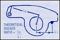 the distance from distance from the point where the rocker tip touches the valve to the fulcrum centreline, divided by the distance from the centre of the pushrod cup or adjusting screw to the fulcrum centreline. 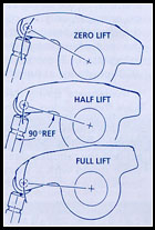 Rocker arm geometry in relation to the installation is critical. Since valve trains have many components, deflection or production tolerances will usually affect the actual valve lift, therefore the theoretical ratio will usually be slightly higher than the rated ratio of the rocker. For this reason it is always a good idea to check the lift of each valve for your application to determine if the valve opening is the same on all the cylinders. Having the proper valvetrain geometry is critical to the system being durable and providing the proper valve lift. |
The tip of the rocker should operate
around the centreline of the valve stem when the rocker opens
the valve. Locating the rocker properly is achieved by moving mounting points, combining different length pushrods and valve stems or changing rockers. The roller tip should ideally contact the valve stem centre when the valve is at half lift. If it contacts the stem towards the outside of the head, the pushrod is too long or if the contact is toward the fulcrum, the pushrod is too short. The easiest way to check roller/valve tip relationship is to apply a very light smear of 'bearing blue' (Available from auto parts suppliers) to the tip of the valve, then carefully assemble the rocker/rockers to the cylinder head. Once the valve has opened and closed, you can clearly see the 'contact patch' of the roller. This contact patch should be as close as possible to the centre of the valve and as thin as possible to minimise the amount of side loading on the valve experienced under extreme operating conditions. The contact point will be closer to the centre at zero lift than at full lift if the pushrod is too long and vice versa if the pushrod is too short. It is important to note when using rigid mount shaft type or pedestal type rockers, the mounting pedestal or spacer height may need to be altered to make geometry changes. |
![]()
|
The primary advantage of the stud type rocker assembly is that its geometry
is self compensating for changes in cam lift, as the pivot point is not fixed and is
free to move up and down the stud. When the lift at the cam is increased, the base circle radius of the cam is reduced by a like amount. This reduced base circle radius lowers the tappet height when on the heel of the cam and the pushrod end of the rocker arm is lowered by a like amount. The dimension of each component in the valve train is critical to the overall geometry. Check all dimensions starting at the base circle of the cam and including the length of the tappet or lifter, the pushrod and the valve stem height. If the valves are changed or modified, it is important to retain the stock stem dimension measured from the spring seat to the tip of the valve. With stud type rockers, if a longer stem valve must be used, this must be compensated for by installing longer pushrods and in the case of shaft type rockers, increasing the pedestal height. In addition, any material milled off the block or head surface will tend to upset the geometry and excessive milling must be compensated for by installing shorter pushrods. With high lift camshafts, the clearance of .040" - .060" between the elongated slot in the rocker and posilok nut and the rocker and pedestal or stud must be checked on the pushrod side, with the valve closed and on the valve side with the valve fully open. |
If larger than standard valve
springs and retainers are used, in the case of stud type
rockers, check that there is .060" clearance between the
retainers and the underside of the rocker arm throughout the
entire valve lift. Because of the rigidity of shaft type rockers .040" clearance is adequate. Rocker notching may be necessary in extreme cases, this should be done correctly – preferably by our factory as improper modifications will weaken the arm and void your warranty. It may be necessary to mill or turn material off the bottom of the rocker shaft pedestals to correct the geometry. The amount must be calculated for each application as this is determined by the change in lift over stock, the rocker arm dimensions and the rocker arm ratio. Care must be taken when shaft type rocker arms with adjusting screws are used with high lift cams. Any decrease in the base circle must be compensated for by the adjustment screw and in extreme cases, the screw can become extended far beyond the original design limits of a maximum of three turns out. This situation not only overloads the screw with breakage a possibility, but will upset the rocker arm geometry and change the rocker ratio. This condition is easily corrected by installing longer pushrods, shorter pedestals, or perhaps lash caps. |